CTE Metals & Fabrication · Crescent Valley HS

CNC Plasma Cutting
Complete Student Guide

From concept to finished cut part on our Arclight CNC plasma table. Follow the sections below — each builds on the last.
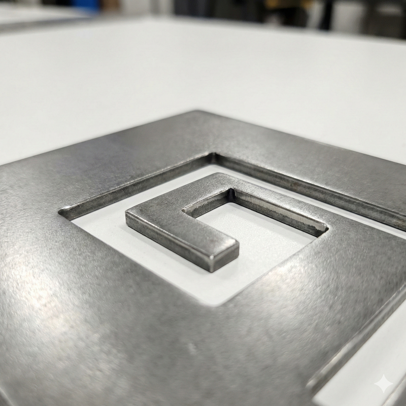
Finished CNC plasma cut sign in steel
Mr. McAteer Arclight Arc Pro · Hypertherm Powermax45 SheetCam 6.1.38 · CommandCNC 2.7.8
Arclight Arc Pro
CNC Table
Powermax 45
Plasma Source
45A Shielded
Consumables
SheetCam 6.1.38
CAM Software
CommandCNC 2.7.8
Controller
1
Concept
Idea or AI image
→
2
Design
SolidWorks · Illustrator
.sldprt .ai
→
3
Export
Save As DXF or SVG
.dxf .svg
→
4
CAM
SheetCam
Toolpaths → .tap
→
5
Cut
CommandCNC
Load → Run
1

Understand: How CNC Plasma Cutting Works The science, the machine, and the software pipeline.

What Is Plasma?

Matter exists in four states. Add enough energy and matter transforms from one state to the next. Plasma is the fourth state — gas so hot it becomes electrically conductive.

🧊
Solid
Ice
→
💧
Liquid
Water
→
♨️
Gas
Steam
→
⚡
Plasma
40,000°F

How the Cut Happens

Compressed air is forced through a tiny nozzle orifice in the torch.
A pilot arc sparks between the electrode (negative) and the nozzle (positive) inside the torch, ionizing the gas.
The ionized gas contacts the workpiece, creating a transferred arc from electrode → workpiece.
The constricted arc superheats to ~40,000°F — roughly 7× hotter than the surface of the sun — melting the metal.
High-velocity gas blows the molten metal away, creating a narrow cut called the kerf.
🔥
Key concept: Plasma cutting only works on electrically conductive materials — steel, aluminum, stainless, copper, brass. It cannot cut wood, plastic, glass, or stone.

The Software Pipeline: CAD → CAM → CNC

StageSoftwareWhat It DoesOutput
CADSolidWorks, Illustrator, InkscapeYou design the shape. 2D geometry with closed contours..DXF or .SVG
CAMSheetCamConverts geometry to a toolpath — adds kerf offset, lead-ins, pierce points, feed rates..TAP G-code
CNCCommandCNCReads G-code and drives the motors. Controls torch on/off, THC, pause/resume.Finished part
✅
Our workflow: Design at your workstation → export DXF to USB → walk to the plasma station → SheetCam & CommandCNC run on the Arclight's built-in computer.
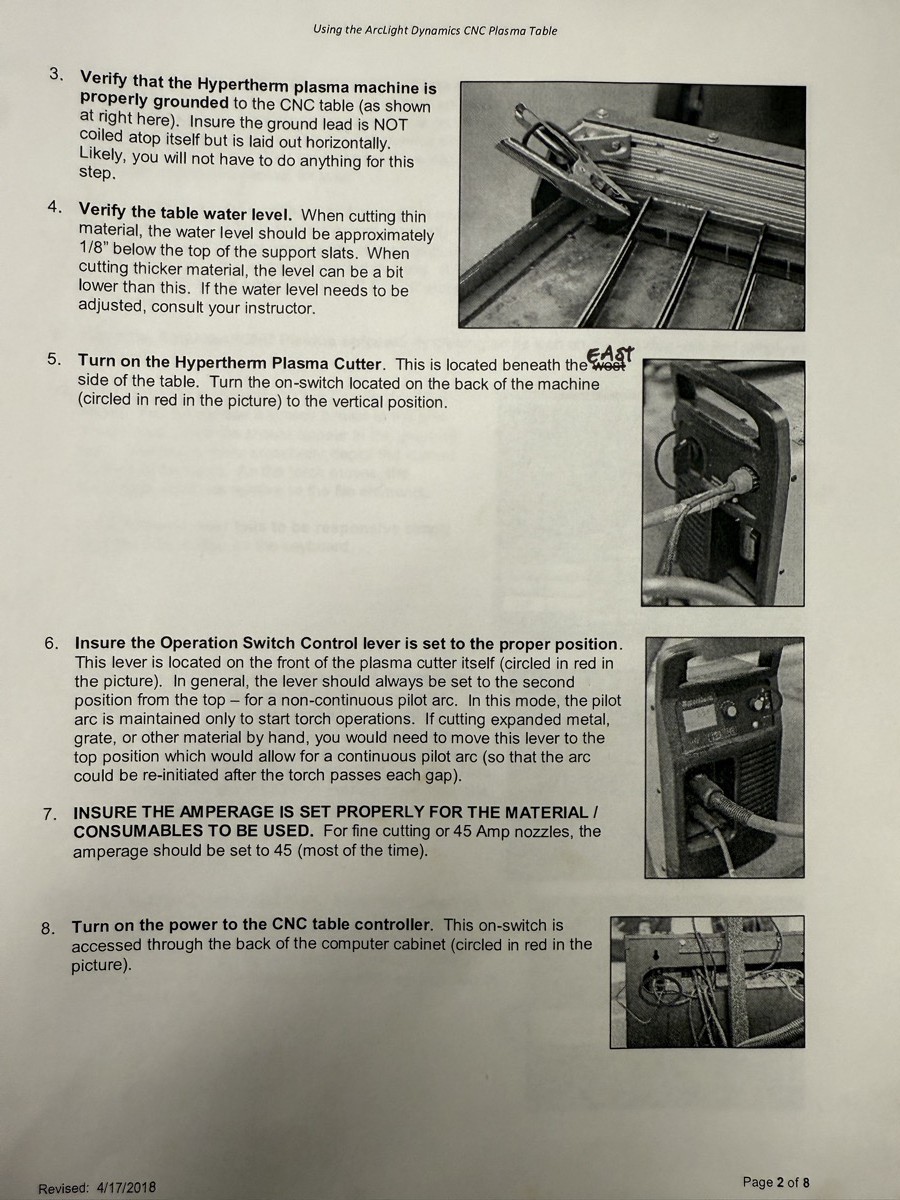
Arclight CNC plasma table showing air supply, water table, and ground clamp setup
Machine setup reference: Air supply connection, water table level verification, Hypertherm power switch location, and ground clamp positioning. From the Arclight Dynamics user manual.

Torch Height Control (THC)

The distance between the torch tip and the metal — called standoff — directly controls cut quality. Our Arclight includes automatic Torch Height Control that maintains the correct height even on warped steel:

Initial Height Sensing (IHS): Before each cut, the torch lowers until it touches the plate, establishing a Z-zero reference.
Pierce Height: Torch raises to a safe pierce height and the arc fires. This protects the nozzle from molten blowback.
Cut Height via Arc Voltage: THC reads arc voltage in real-time. Higher voltage = torch too far → lowers. Lower voltage = torch too close → raises. Happens many times per second.
2

Design: Create Your Artwork Start in SolidWorks, Illustrator, or with an AI-generated image. Fix islands before export.

Option A: AI Image → SolidWorks Autotrace

Generate a plasma-ready silhouette with AI, then trace it in SolidWorks:

"Create a high-contrast black and white silhouette of [subject]. Solid black shapes on pure white background. No gradients, no gray tones, no shading. All interior details must be connected to the outer border with visible bridges. Design it as a single continuous stencil — no floating pieces. Clean vector-style edges, minimum detail width 3mm."

SolidWorks Autotrace Steps

Enable Add-In: Tools → Add-Ins → check Autotrace
New Part → open sketch on Front Plane
Insert image: Tools → Sketch Tools → Sketch Picture → select your PNG
Scale image to your desired final cut size now (not later)
Click the → arrow in Sketch Picture panel to enter Autotrace mode
Select area with rectangle tool → click Begin Trace
Adjust Color Tolerance ↑ and Recognition Tolerance ↓ until outlines are clean
Click Apply → repeat for missed areas → OK

⚠ Fix Floating Islands — The #1 Fail Point

An "island" is any enclosed interior shape not connected to the main body. When the plasma cuts around it, the island falls into the water table. Letters like A B D O P Q R all have islands. So do eyes, nostrils, windows, and any interior detail.

✗ No Bridges — Falls Out

A B D O

Interior pieces have nothing holding them. They drop through.

✓ Bridged — Stays Connected

A B D O

Small tabs/bridges connect each interior to the outer body.

How to Add Bridges in SolidWorks

  • Zoom into each island → draw a small rectangle spanning the gap
  • Bridge width: ≥ material thickness (minimum 1/16" for 16ga, 3/32" for 12ga)
  • Use Trim Entities tool to merge the bridge into the path
  • Place bridges where they look natural — 2 bridges per island for large pieces
3

Export: DXF or SVG for SheetCam Choose the right format and settings for your design software.

Export Settings by Software

SoftwareExport AsCritical Settings
SolidWorks .DXF R12/R14 format · ☑ Splines as polylines · ☑ High Quality DWG · ☑ Merge Points · Scale 1:1
Illustrator .SVG File → Export As → SVG · Profile: SVG 1.1 · Type: Convert to Outline · Never export DXF from AI
Inkscape .SVG Plain SVG (not Inkscape SVG) · Path → Object to Path first · Combine all paths (Ctrl+K)
⚠
Illustrator DXF exports are broken. Adobe segments arcs into hundreds of tiny line fragments. Always use SVG from Illustrator — SheetCam reads it at 1:1 scale with clean geometry.

DXF vs SVG — When to Use Each

DXF

  • Use from: SolidWorks, AutoCAD, QCAD
  • Must be R12/R14 with polylines + arcs
  • True arcs = cleanest geometry possible
  • Industry standard for engineering drawings
  • Splines cause jagged cuts in SheetCam

SVG

  • Use from: Illustrator, Inkscape, web graphics
  • Imports at 1:1 scale — no sizing issues
  • Fewer nodes = smoother toolpaths
  • Best for artistic/sign work & logos
  • SheetCam handles SVG very well
💡
Rule of thumb: Engineering parts → DXF from SolidWorks. Art, signs, logos → SVG from Illustrator or Inkscape.

SolidWorks → DXF Quick Steps

Delete the sketch picture (image). Only sketch geometry should remain.
Right-click flat face → Export to DXF/DWG
Set format to R12 · Check "Splines as Polylines"
Check "High Quality DWG" + "Merge Points" · Scale 1:1
Remove all dimensions, notes, and title blocks
Save to USB: LastF_ProjectName.dxf
4

SheetCam: Generate Toolpaths Import your file, select the right tool for your gauge, create operations, verify, and post-process.

⛔
THE #1 RULE: SheetCam applies kerf compensation automatically. Your DXF should be drawn at exact final size. If you already pre-compensated in SolidWorks, your part will be the wrong size. Do not double-compensate.
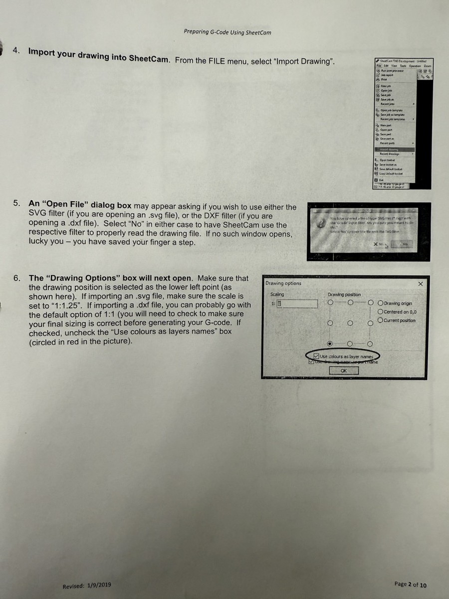
SheetCam interface showing DXF import and drawing options
SheetCam import: File → Import Drawing, set drawing position to lower-left, scaling 1:1. Uncheck "Use colours as layer names" for clean imports.

Step 4.1 — Import Your DXF

File → Import Drawing → navigate to USB, select your .dxf file. If prompted about units, choose Inches.
Check scale immediately: Hover over a known dimension and read coordinates at the bottom. If your 12" sign shows as 6" — re-export. Do not scale in SheetCam.
Check for red outlines = floating pieces with no bridge. If you see red on letter interiors (O, A, D, B) — stop and go back to add bridges.

Step 4.2 — Select the Correct Tool for Your Gauge

Open the tool table: Tools → Tool Table. Select the existing tool for your material gauge, or create one using these values from the Hypertherm Powermax45 Duramax cut charts at 45A shielded, mild steel:

Setting16 GA (0.060")14 GA (0.075")12 GA (0.105")
Tool NamePM45-16ga-45APM45-14ga-45APM45-12ga-45A
Kerf Width0.039"0.043"0.049"
Feed Rate200 IPM160 IPM110 IPM
Pierce Height0.150"0.150"0.150"
Pierce Delay0.4 sec0.5 sec0.8 sec
Cut Height0.060"0.060"0.060"
Plunge Rate100 IPM100 IPM100 IPM
✅
Pro tip: Create and save all three tools, then go to File → Save Default Toolset so they load automatically every session. You only pick the right one per job.
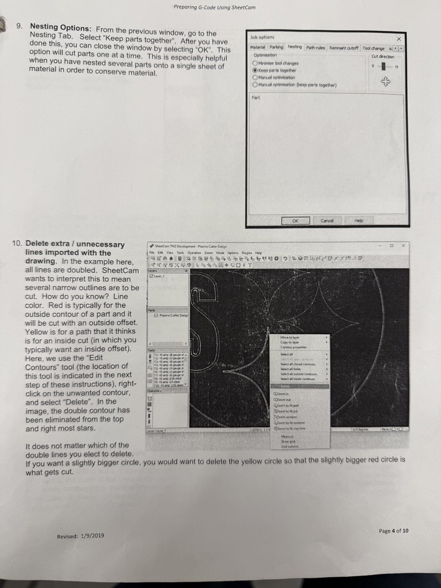
SheetCam contour operation showing toolpath setup and job options
SheetCam job options and contour operation: Set material dimensions (48" × 96" for a standard sheet), verify nesting, and create contour operations with correct offset direction.

Step 4.3 — Create a Contour Operation

Operations → New Contour Operation (or the blue contour icon in toolbar)
Select your tool from the dropdown (e.g., PM45-14ga-45A). All values auto-populate.
Set offset direction: Outside offset for perimeter cuts. Inside offset for holes and interior cutouts. Never "No offset" for cutting.
Lead-in type: Arc (preferred) at 0.125" radius. Lead-in should start on scrap side, not on your finished edge.
Cut interior features first, then outside profiles last. Create separate operations if needed.
For detailed signs: check Loop sharp corners to compensate for arc lag at corners.
⛔
Offset mistake: If outside profile = Inside offset, or holes = Outside offset, SheetCam compensates the wrong direction. Your part shrinks or grows by the full kerf width. Outside contours = Outside offset. Interior = Inside offset. Always.

Step 4.4 — Verify Toolpaths & Post-Process

Visual Check

  • Blue toolpath = outside cuts
  • Green toolpath = inside cuts
  • Red contours = unassigned/island — must fix
  • Arrow direction: Outside = CW, Inside = CCW
  • Lead-in dots on scrap side

Simulate & Post

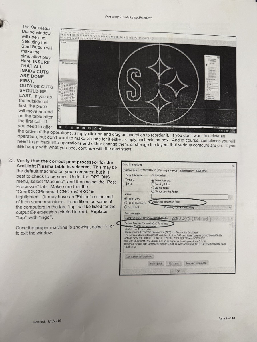
  • Click Simulate — watch the cut animate
  • Verify: inside features cut first, no overlaps
  • Options → Machine → Post Processor must read CommandCNC
  • File → Run Post Processor
  • Save to USB as LastF_ProjectName.tap
SheetCam showing simulation preview and post processor settings
Verify & post: Simulation preview with toolpath animation (left). Ensure all inner cuts are done before outside profiles. Post processor must be set to CommandCNC/CandCNC format.
5

Cut: CommandCNC Machine Operation Safety checks, consumables, homing, zeroing, dry run, and live cut.

⛔
BEFORE TOUCHING THE MACHINE — EVERY TIME: Safety glasses ON · Welding shade nearby (shade 5+) · No loose clothing · Water table filled to slat level · Air compressor ON, 85+ PSI · Ground clamp secure on material · E-stop accessible

Check Consumables Before Every Session

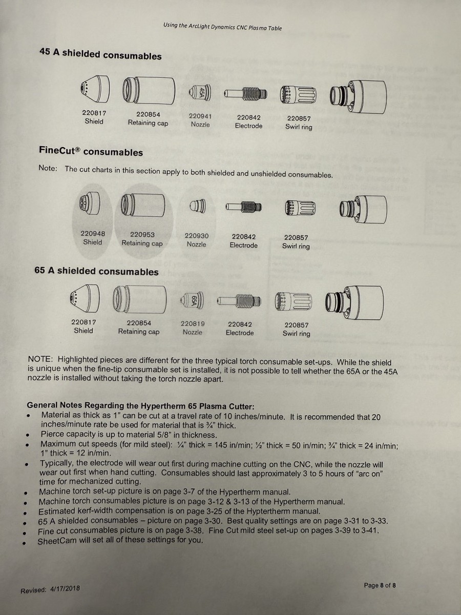
Worn consumables cause bad cut quality, excessive dross, and failed pierces — no amount of software tweaking fixes worn parts.
⬥
Nozzle
Replace when hole is oval, oversized, or gouged. Most common wear part.
⬢
Electrode
Replace when hafnium pit depth exceeds 0.040" (~1mm).
◎
Swirl Ring
Check for cracks or melted holes. Longest-lasting part.
□
Shield
Inspect for buildup/damage. Dirty shield = poor arc stability.
Hypertherm Powermax consumable parts diagram showing 45A shielded, FineCut, and 65A configurations
Consumable reference: 45A shielded consumables (top row) for all 12/14/16 gauge mild steel. Match amps to consumable rating — always. Part numbers shown for reordering.

CommandCNC Workflow

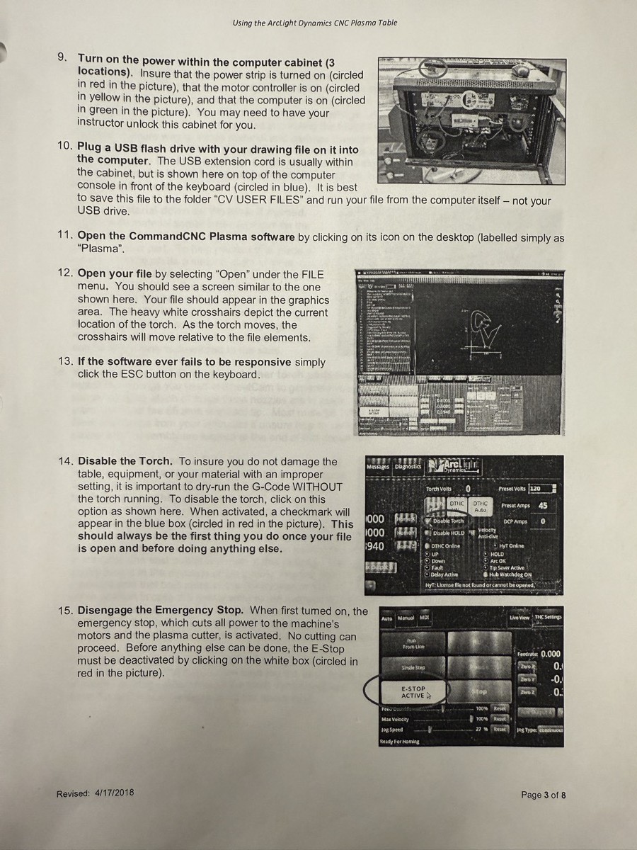
Power On & Release E-Stop. Press the green arm button on the Blade Runner box. Release E-stop in CommandCNC. Verify no axis alarms.
Home All Axes. Click Home All. Wait until each axis shows Homed. This is the machine's internal reference — not your part zero.
Set Torch Disable = ON. CRITICAL. Prevents torch from firing during jogging or dry runs. Only turn OFF when actually cutting.
Load G-Code: File → Open → navigate to USB → select your .tap file. Verify the shape looks correct in the preview.
Jog to Program Origin & Zero X/Y: Move torch to the lower-left corner of where you want the cut. Click Zero X and Zero Y. Do NOT zero Z — the IHS probe handles Z automatically.
📚
Homing vs Zeroing: Homing (step 2) tells the machine where it is. Zeroing (step 5) tells the machine where your part is. You home once on startup. You re-zero for every new part position.
CommandCNC interface showing program loading, torch disable, and dry run procedure
CommandCNC operation: Loading file from USB (top-left), torch disable toggle, E-stop location, and the dry run sequence. Always dry run before live cutting.

Dry Run → Live Cut

Dry Run: Confirm Torch Disable is ON. Press Cycle Start. The gantry traces the entire program without firing. Watch for clearance, cut order, and fit on your sheet.
Turn Torch Disable OFF. This is the only time you turn it off. Everyone clear of the table. Welding shade available.
Verify THC = Auto/Enabled on the CommandCNC screen.
Press Cycle Start — Monitor the Cut. Watch actively. Keep one hand near Feed Hold or E-stop. Look for clean arc, minimal topside sparks, steady sound, no torch dragging.

Adjustable During Cut

  • Feed Rate Override: ± speed via knob or screen
  • THC Voltage: ± target (raise = lower torch)
  • Feed Hold: Pauses cut. Resume with Cycle Start.

Never Do During Cut

  • Touch material — hot metal, arc, water splash
  • Walk away — operator must be present entire cut
  • Move ground clamp — arc transfer failure
  • Jog axes — lose position and crash
✅
After the cut: Turn Torch Disable back ON. Let the piece cool. Remove from table, clean dross with flap disk or wire wheel, and verify dimensions with calipers. If dimensions are off by exactly one kerf width — you had the wrong offset direction.
T

Troubleshooting Common failures, symptoms, causes, and fixes.

ProblemWhat You SeeCauseFix
Heavy dross bottomHard metal beads stuck to undersideCutting too slowIncrease feed rate 10–15%
Feathery dross topWispy metal curls on top edgeCutting too fastDecrease feed rate 10%. Check consumables.
Failed pierceTorch fires but doesn't break throughPierce delay too short, or worn partsIncrease pierce delay +0.2s. Replace consumables.
Torch divingNozzle crashes into plateIHS failure or THC overcorrectingCheck IHS switch. Disable THC for small features.
Part wrong sizeDimensions off by kerf widthWrong offset direction or double kerfOutside = outside offset. Inside = inside. No pre-compensation.
Rounded cornersSharp corners cut as arcsArc lag at cornersEnable Loop sharp corners in SheetCam.
Pieces falling outInterior features drop into waterFloating islands — no bridgesGo back to SolidWorks. Add bridges at material thickness.
Arc OK errorTorch fires briefly, extinguishesGround clamp not on materialMove ground clamp to bare metal. Replace consumables.
✓

Pre-Cut Checklist Complete at the station before every job.

  • Air pressure: 85+ PSI, Powermax reads 60 PSI cut pressure
  • Consumables: Nozzle and electrode inspected
  • Powermax amperage: Dial set to 45A
  • Water table: Filled to slat level
  • Ground clamp: On bare metal on workpiece
  • Material secured: Flat on slats, not rocking
  • Correct tool: Right gauge selected in SheetCam
  • Post processor: CommandCNC post used
  • Offset direction: Outside = outside, interior = inside
  • Toolpaths verified: Simulated, arrows correct
  • No red outlines: All features bridged
  • All axes homed in CommandCNC
  • X/Y zeroed at program start on material
  • Dry run complete: With Torch Disable ON
  • THC: Set to Auto/Enabled
  • Safety: Glasses, shade, area clear, E-stop ready
⚙

Quick Reference Numbers you'll use on every cut. Hypertherm Powermax45 @ 45A Shielded, Mild Steel.

16 GA
Kerf: 0.039" · Feed: 200 IPM · Pierce: 0.4s
14 GA
Kerf: 0.043" · Feed: 160 IPM · Pierce: 0.5s
12 GA
Kerf: 0.049" · Feed: 110 IPM · Pierce: 0.8s
💪
Nickel test: No feature should be thinner than the edge of a nickel (~0.077"). If you can't fit a nickel in the gap, it's too thin to survive the cut. Minimum feature = 2× kerf width for your gauge.
GaugeThicknessKerf WidthMin FeatureMin BridgeFeed RatePierce Delay
16 GA0.060"0.039"0.080"0.063" (1/16")200 IPM0.4 sec
14 GA0.075"0.043"0.090"0.075" (5/64")160 IPM0.5 sec
12 GA0.105"0.049"0.100"0.105" (3/32")110 IPM0.8 sec

Source: Hypertherm Powermax45 Duramax cut charts (810050) · 45A Shielded · Mild Steel